Ventilator sharing device: System specification
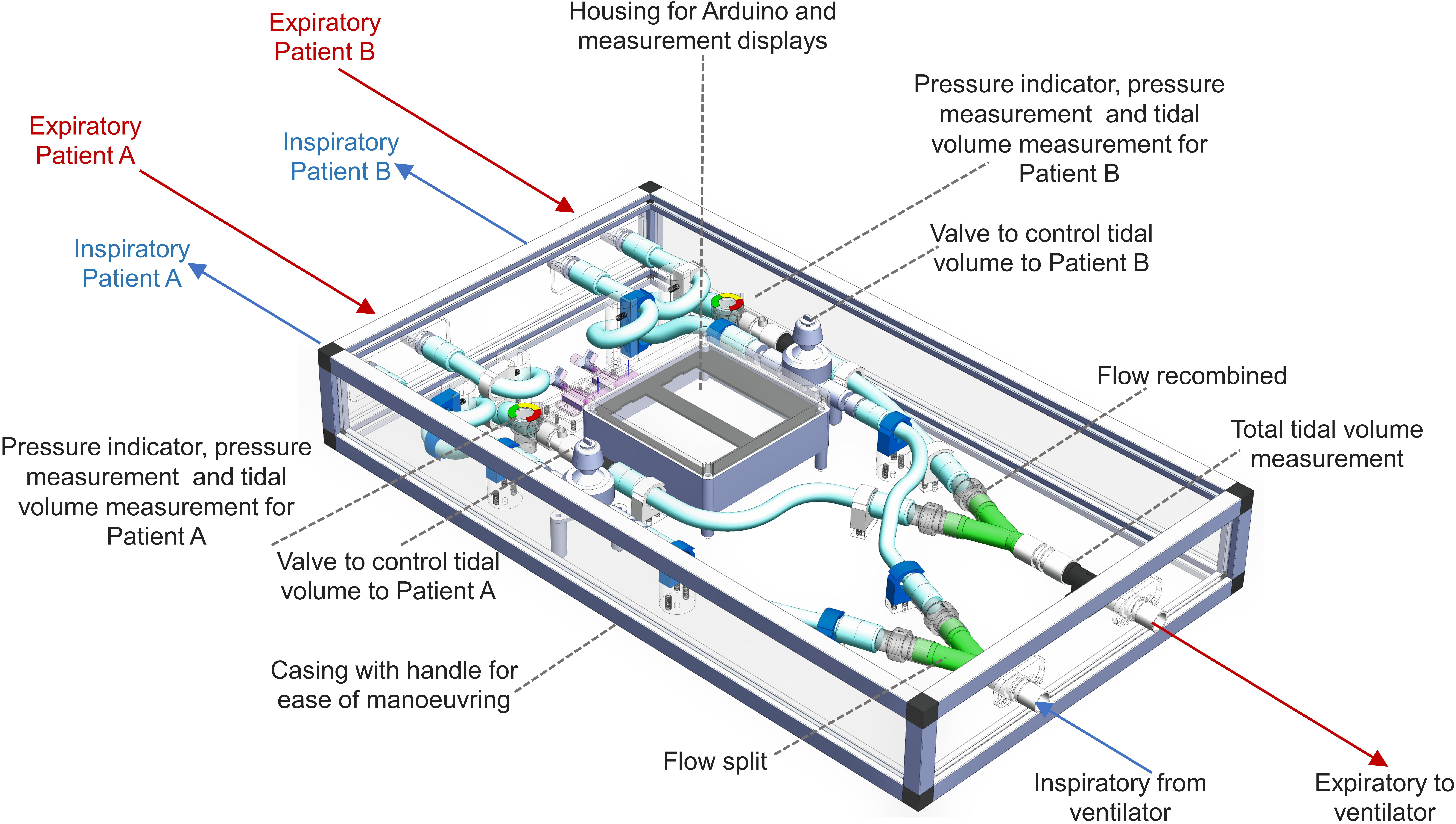
The diagram above illustrates how the device is assembled in a box, with labels showing the respiratory flow for one patient (A).
A clear box has been used and the readout meter is clearly viewed from one side, with patient A’s air pressure and tidal volume readings at the top, followed by patient B’s readings below; a reading of the total tidal volume from both patients taken from a third sensor appears below both patient’s readings, for validation. The size of the box was dictated by the respiratory parts available through the UK supply chain at the time of build. Many of these standard parts can be replaced with similar parts and accordingly the box size could vary in size to house them.
The ventilator connects to the two breathing circuits at one end of the box. A standard Y-connector is used just after both the inhalation and exhalation connection ports, in order to split the air flow for each patient and recombine the airflow, respectively. One-way valves (check valves) are attached to each of the Y-splitters, both on the inspiratory and expiratory flow connections, to ensure there is no contamination between patients and to maintain pressure in the system. Each patient’s breathing circuit has a flow control valve that can be manually controlled to change the air flow from the ventilator to the individual patient. Measurements are made on the expiratory flow with a visual pressure gauge, a pressure port which is attached to a pressure sensor for digital readout, and a flow sensor. The full hardware and software specification of the readout meter will be uploaded online in the near future once testing is complete.
Full details of the system specification will be uploaded in the near future.
Video walkthrough of system components
Find out more about: