High speed patterning of individual carbon nanotubes
Field emission
The need for this research stemmed from work considering field emission from carbon nanotubes. The requirements for good electron field emission include having a sharp tip with a high conductivity, high aspect ratio, high chemical stability and high mechanical strength. A carbon nanotube fulfils these requirements very well but when they are grown without a patterned catalyst the resulting structure is a dense forest of nanotubes with very few protruding enough to enable a high aspect ratio emitter as shown in Figure 1.
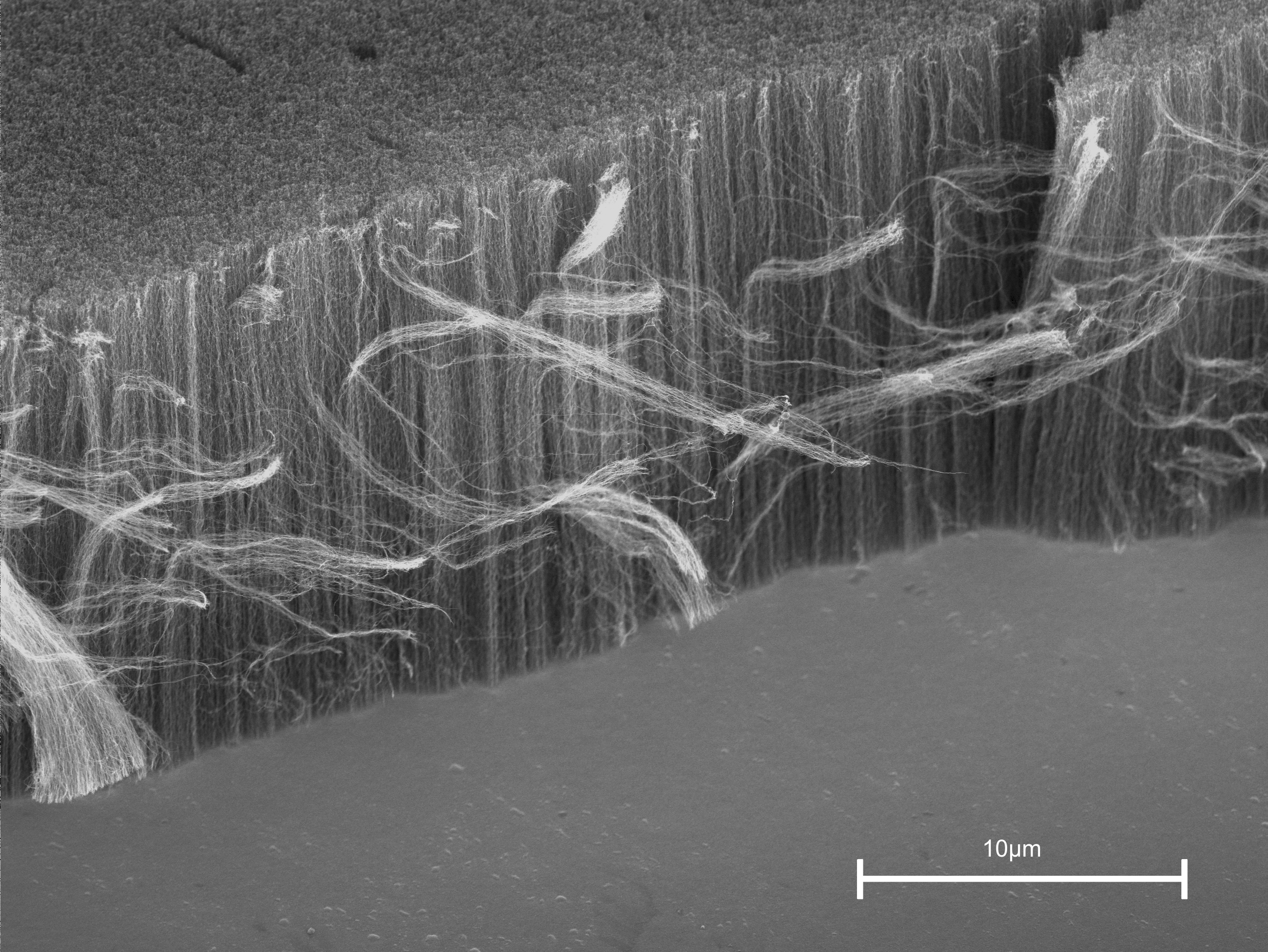
Figure 1 - Carbon nanotube forest
Patterned catalyst
For research purposes, generally a 10mm square wafer is used because this size is easily manageable. Ideally the pattern would cover the entire area, but for carbon nanotubes an area up to 1mm on the wafer is sufficient for most measurements and analysis. The most common method for this is using electron beam lithography which enables very high resolution (can easily provide the required 100nm catalyst) but it is a serial process and generally requires a planar substrate to avoid focus variations due to the shallow depth of field. This makes it a slow and costly process.
Combining a lift off process with focussed ion beam (FIB) milling yields favourable results for small samples. Figure 2 shows holes milled in PMMA which took 1.2 seconds. If a thinner PMMA layer was used this speed would increase further. To enable the growth of nanotubes a suitable metal is deposited into the holes and the PMMA is removed to leave well defined catalyst dots.
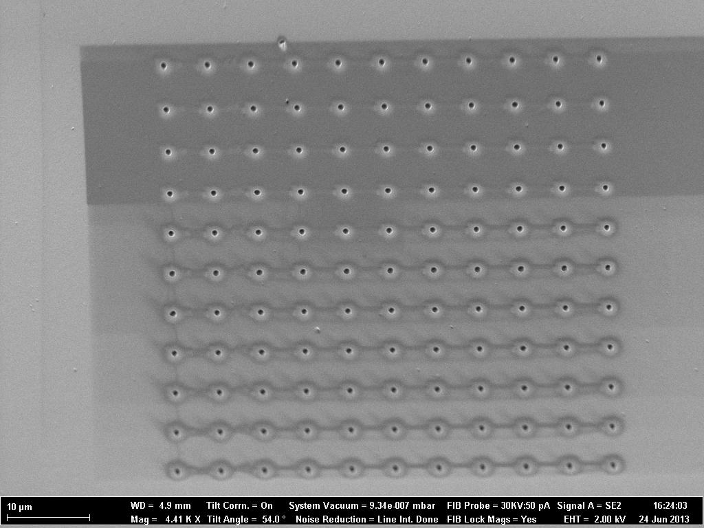
Figure 2 - FIB milled holes
For research purposes the FIB is particularly useful, however there are problems involved if the technique needs to be scaled up. Figure 3 shows the locus of the ion beam with the source being located at i. It can clearly be seen that perfect focus of the beam is only achievable at one point directly below the source. Resolution is lost when the beam is deflected away from this point to cover a larger area. The only way to achieve acceptable results over a large area is to move the sample itself which slows down the whole process.
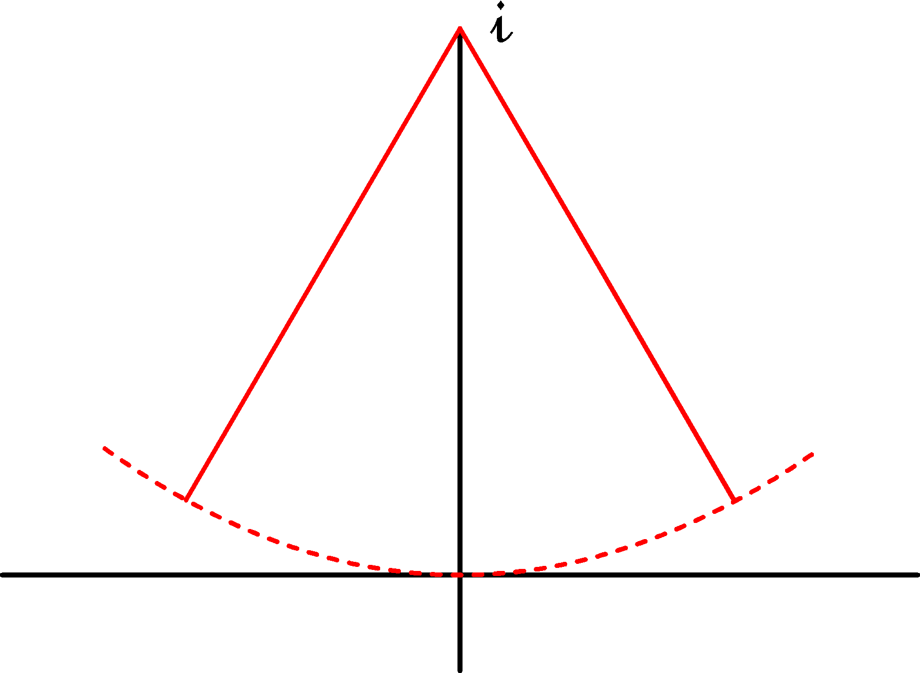
Figure 3 - Ion beam locus
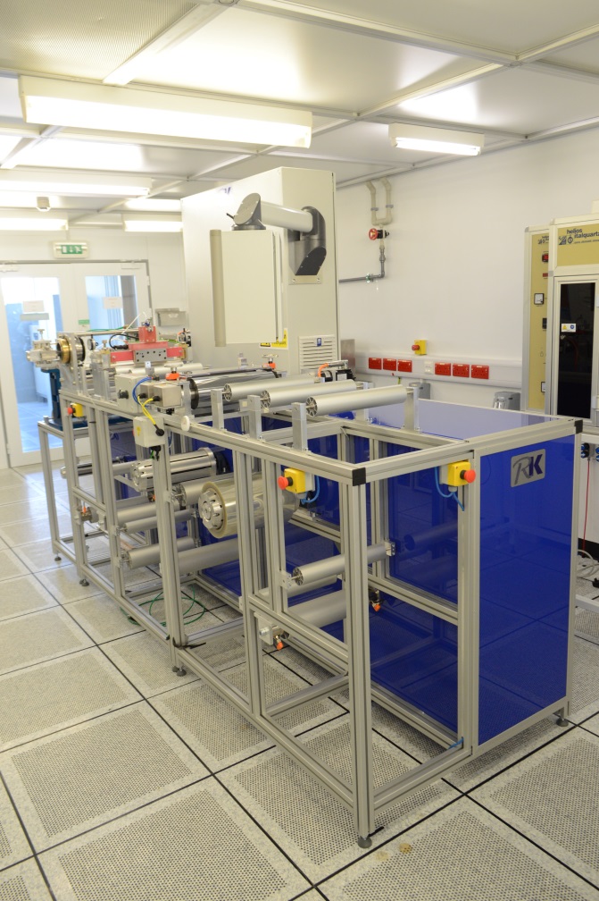
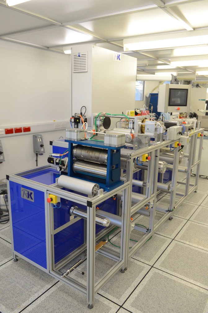
A further area being considered is the incorporation of CNT fabrication onto a roll to roll system. We have recently invested in a versatile roll to roll facility (Figure 4) which allows for excellent control of film speed and tension. Addition of further stages has been envisaged and can be incorporated into the system relatively easily. If research determines that a particular catalyst material is needed for larger areas, then a suitable colloid could be considered and incorporated into a nano-contact printer. The resolution and repeatability of this method will not be as good as FIB or e-beam but it will have a significant advantage in the throughput achievable.
 |
 |
|
Figure 4 - Roll to roll system |
|
Researchers
- C. Williamson
- D. Chu