ISO Compliant Online Laser Beam Monitoring
The measurement of high speed laser beam parameters during processing is a topic that has seen growing attention over the last few years as quality assurance places greater demand on the monitoring of the manufacturing process. The targets for any monitoring system are to be non-intrusive, low cost, simple to operate, high speed and capable of operation in process.
High power, fast axial flow CO2 laser beams are not stable. They are constantly moving, varying in power, and changing in intensity. Non-intrusive online beam monitoring will be a major step towards assuring beam quality management for laser processing. Without monitoring, slack, open-loop processing envelopes are required. In process monitoring will remove uncertainty, allowing the processing performance limits to be explored yielding:
- lower costs through reduced scrap, faster processing, and reduced setup and down time
- extended processing applications due to smaller, known processing variations
- improved safety through remote monitoring of beam parameters at all times
Aim
To develop a demonstration system to provide measurements of relative power, and ISO standard measurements of beam diameter and position, for commercial 'lights out' processing facilities. The device will not be a “high end” lab based unit, a number of which can already be purchased, but instead a device more suited to installation in the price conscious industrial market.
Technology
For in-process diagnostics the main power beam must be able to propagate to the process area unimpeded and a small sample of the beam taken for analysis. The sampling optic used for this work is a Silicon based mirror. This mirror reflects almost 100% of the energy from the front surface approximately 0.1% being propagated through the mirror for analysis. Silicon was selected as the substrate as is already a widely used substrate in the high laser power arena, being valued for its lightweight, high conductivity and low cost.
Once the beam has been sampled it is necessary to analyse the sampled radiation. This was done using:
1. Reference analysis
The raw, un-sampled beam was measured using UFF100 and UM110 analysers. These are both devices which directly sample small amounts of the high power beam and build up a picture of the beam structure over time. The use of these devices permits the fidelity of the sampled beam to be checked.
The fidelity of the sampled beam was examined using a Spiricon Pyroelectric camera. This is the market leading/ reference CO2 camera laser beam analyser, but comes at a considerable cost. The high cost makes them suitable for research environments and laser manufacturers, rarely end users.
2. Tested analysis techniques
Micro bolometer and Thermopile cameras were both examined as potential low cost replacements for the Pyroelectric camera. The microbolometer proved to be too sensitive for the optical arrangement, and was easily damaged. Continued use of this device would require the addition of a variety of expensive optics, defeating one of the primary targets. The Thermopile camera had internal reflections from the sensing array preventing accurate results being obtained.
An alternative technique using UV pumped infrared to visible converters (a Macken Instruments IR view screen), and the ultimate low cost camera…a web cam proved more interesting.
Optical performance modelling
The performance of the optic and mounting is primary to the success of the system. If a sampling optic can not be used which is thermally stable and gives representative sampling the system can not work.
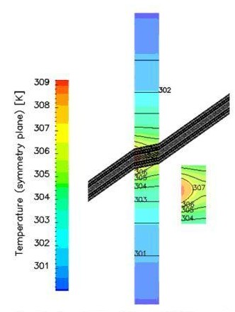
The Silicon optic was simulated to highlight potential sources of measurement error. At first a thermal simulation was performed to evaluate the inhomogeneous temperature field due to surface absorption and transmission of the laser beam. This temperature data was then used in a subsequent stress analysis to evaluate maximum displacement of the mirror surface. Once it was established that this does only introduce an insignificant geometrical non-linearity, the transmitted laser beam was traced through the resulting inhomogeneous refractive index field in order to gauge if the assumption of straight path (i.e. that the refractive index was assumed constant and deformations were disregarded) in the thermal model is valid and to quantify the effect on the measured beam behind the mirror.
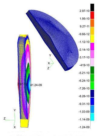
A thermal model of the mirror using a worst case, a 6kW beam with a 9.6mm 1/e2 waist. This showed a maximum temperature rise of 9K, giving a mirror displacement of 1.24x10⁻⁹m – less than a thousandth of a wavelength.
 |
 |
| Temperature profile on symmetry plane with traced ray |
Fringe plot of axial displacements and deformed mesh of mirror |
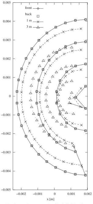
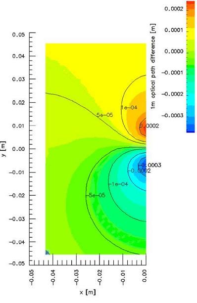
Optical ray tracing through the distorted optic showed negligible variation on beam propagation at distances of 1m and 3m (far in excess of the distance to the camera). Optical path difference was also considered (potentially resulting in interference effects) and no problems could be seen.
 |
 |
|
Spot diagram of input, output, 1 and 3m behind the mirror |
Optical path difference to 1m position
|
Diagnostic results
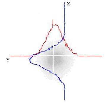
A typical result from the webcam (converted to black and white) can be seen in the figure below. Relative intensity profiles through the centre of energy are overlaid with the red and blue lines.
 |
|
IR view screen of diameter 8.3mm DC010 beam, 500W (S7)
|
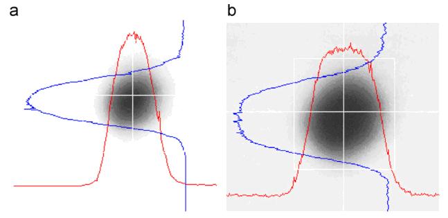
The intensity of the received image is however also a result of the intensity of the UV pump light, images of the same beam being shown in the examples below, for a the UV pump is bright, and for b dim.
 |
|
IR view screen of diameter 8.3mm DC010 beam, 500W (S7)
|
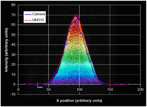
Once the system has been configured correctly and calibrated the overall performance of the final system can be assessed. The illustration below shows a multicolour Spiricon camera image taken behind the silicon mirror, a UM110 trace (red line taken on the raw beam) and a webcam section (blue line). These show that the sampled beam is representative of the raw beam, and that the webcam produces results that can be reasonably approximated the Pyrocam.
 |
|
Normalised comparison of Spiricon, UM110 and visible camera
|
Conclusion
The potential for using a silicon based optic as a direct sampling device has been shown. The optic is an adaptation of commonly used configuration, and as such should not be problematic for introduction into a commercial arena. Power transmission has been shown to be linear, and the sampled beam representative of the incident. Analysis of the transmitted data can be achieved either using commercial high quality systems, like the Spiricon Pyrocam, or, if such high performance is not needed, lower cost more simple solutions. Thermal modelling of the optic when considering even extreme cases of high powers on small areas has demonstrated the stability of the optic, without the need for active water cooling. Simple air jets can be used to maintain cleanliness of optic, and distortion to
Publications
- Sparkes, M. and Gross, M. and O'Neill, W. (2008) A novel non-intrusive sampling technique for CO2 laser on-line beam monitoring utilising a silicon mirror in Optics and Lasers in Engineering, 46 (8). pp. 620-627. ISSN 0143-8166
- Sparkes, M. and O'Neill, W. (2003) On-line measurement of critical laser beam properties in The Industrial Laser User, 32 . p. 38. ISSN 1366-963X
Collaborators
Infratec inc
BNFL
Funding
Researchers
C. Holland
Duration
2004-2005